WORKING PRINCIPAL

The work takes place at impeller which accelerates the liquid by whirling it through the impeller thus adding centrifugal force and hence acceleration.
When an object is spun around in a circle it is accelerated outward by centrifugal force
When liquid is spun around in a circle, it accelerates outward from the center of the circle due to centrifugal force


Liquid enters the pump suction (nozzle) and then into the eye (center) of the impeller.
When the impeller rotates, it spins the liquid sitting between the vanes outward and provides centrifugal acceleration.
As liquid leaves the eye of the impeller, a low-pressure area is created causing more liquid to flow toward the inlet. Because the impeller blades are curved, the fluid is pushed in a tangential and radial direction by the centrifugal force.


Conversion of Kinetic Energy to Pressure Energy

Centrifugal force creates the kinetic energy.
The amount of energy given to the liquid is proportional to the velocity at the edge or vane tip of the impeller. The faster the impeller revolves or the bigger the impeller is, the higher will be the velocity of the liquid at the vane tip and the greater the energy imparted to the liquid.

    TYPES OF PUMP


    CATEGORY: Orientation of Shaft Axis


    Vertical
    commonly installed in a drilled and cased well
    function is to lift liquid (e.g.: fire water pump) from the water level in the well/tank to the surface and provide a specified discharge pressure at the surface.

     
    Horizontal
    pump is aligned horizontally
    function is to transfer liquid and build pressure

    CATEGORY: Number of Stage

     
    Single Stage - has only one impeller


    Double Stage - has two impellers


    Multi Stage - has more than two impellers

    CATEGORY: Casing Split


    Radial split / Vertical split
    • split vertically and the split parts are known as a case and cover
    • used for high temperature applications due to even thermal expansion of the shaft

    Axial Split / Horizontal split
    • split horizontally into two pieces - the upper case and lower case
    • permits removal of the complete rotor without moving either piping or motor
    • limited to temperatures up to 450 ºF. Hotter applications can cause shaft misalignment due to uneven thermal expansion

    CATEGORY: Bearing Support


    Over-Hung 
    the rotor is supported in the form of a cantilever
    impeller is situated at front


    Centre-Hung 
    the impellers on the rotor are supported with bearings on either side
    also called “between-bearing” because impeller is situated in between the bearings

    CATEGORY: Support


    Foot Mounted
    the pump stand on its foot and the foot is bolted to the base plate

     Centre-Line

    the pump has its own base frame

    CATEGORY: Shaft Connection


    End suction / Top discharge
    the suction is situated at the end while discharge at the top

    Top suction / Top discharge
    the suction/discharge line is vertical

    Side suction / Side discharge
    the suction/discharge line is horizontal from the side of the casing

    CATEGORY: Direction of Flow


    Mixed Flow
    specific speed ranges Ns = 3500 to 7000 
    recognized by having screw like impellers
    generally have single inlet
    higher flow


    Axial Flow
    specific speed range Ns = 9000 to 16500
    always single entry and are generally single stage
    pump cases are concentric with inline inlet and outlet connections
    the casing is normally fitted with guide vanes
    highest flow low head designs.


    Radial Flow
    specific speed ranges Ns = 900 to 4500
    advantage of providing a smooth flow and is capable of handling fluids with solids contents
    low flow high head designs

    CATEGORY: Mechanical Construction


    Closed 
    use shrouds that totally enclose the impeller from the suction eye to its edges 
    prevent liquid slippage from the discharge to suction by using a running joint between the casing and the impeller (wear-ring)
    higher pump efficiency


    Semi-open
    uses a single shroud, usually at the back of the impeller
    shroud may or may not have pump out vanes or balance holes to modify the pressure behind the impeller
    can pump thin fluids, heavier fluid and slurry


    Open
    consists of nothing but vanes attached to a central hub
    use to pump thick fluid or slurries
    less efficient than closed impeller


    CATEGORY: Type of Suction


    Double Suction
    equipped with double suction impellers
    develop little axial thrust due to the symmetry of their design
    the flow rate is quite high.
    This can be managed by having one impeller with two suction eye.

     
    Single Suction
    Design to higher axial thrust imbalance flow on one side of the impeller only

    COMPONENTS: Casing


    kinetic energy in the liquid at the outlet is converted to pressure energy by the pump casing
    energy conversion has to be undertaken with a minimal loss to have an insignificant effect on pump efficiency
    fluid leaves the casing through the outlet at a higher pressure
     Volute;
    increases in area from its initial point until it encompasses the full 360° around the impeller and then flares out to the final discharge opening
    wall dividing the initial section and the discharge nozzle portions of the casing is called the tongue of the volute or the “cutwater.”
    Diffuser; 
    a spiral-shaped component surrounding the impeller
    reduce the velocity of a liquid, decrease slippage, and increase ability to develop flow against resistance

    COMPONENTS: Impeller


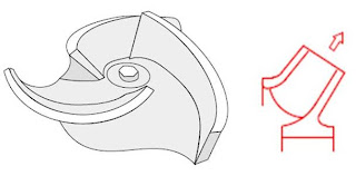
    converts the mechanical rotation to the velocity of the liquid
    acts like the spinning wheel in the pump
    has an inlet eye through which the liquid suction occurs (impeller eye)
    direct the flow of fluid between the vanes
    has vanes that enclosed by metal coverings called metal coverings called “shroud”
    the flows are categorized by the specific speed, Ns

    COMPONENTS: Shaft


    prime mover (motor) drives the impeller and displaces the fluid in the impeller and pump casing through the shaft

    COMPONENTS: Bearing


    rounded pieces of metal (either ball or roller) that support an object and allow it to move smoothly by reducing friction
    to keep the shaft or rotor in correct alignment with the stationary parts under the action of radial or transverse loads

    COMPONENTS: Wearing Ring


    a rotating component and it is housed within the pump casing
    to prevent frictional contact, a gap between impeller and pump casing
    it is essential to keep this gap or clearance at an optimum value to improve the pump’s efficiency

    COMPONENTS: Coupling

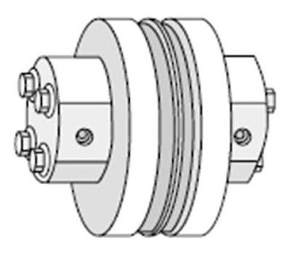
    a power transmission device that is used to connect the motor (driver) shaft to the power end shaft of the pump
    primary purpose of a coupling is to transmit rotary motion and torque from the motor to the pump

    COMPONENTS: Stuffing Box


    a chamber or a housing that serves to seal the shaft where it passes through the pump casing
    consist of packing rings and a gland (end plate) for squeezing and pressing them down the shaft

    COMPONENTS: Packing / Mechanical Seal

    Packing

    Strong flexible ring material that’s control leakage from a stuffing box or cylinder. The present day packing used in pumps are predominantly made of PTFE (Teflon)/Graphite filaments. 

    Mechanical Seal
    A ring-shaped parts that reduce or prevent leaking


    API-610

    A critical refinery pump handling hazardous hydrocarbons would be in all probability built as per standard API 610.

    API 610 standard for centrifugal pumps provides guidelines on the minimum recommended wearing ring clearance in line with the pumping temperatures, thermal expansion, and the efficiency of the pump. 
    E.g.: Horizontal pumps with a centerline support are selected: 
    API 610 recommends pumping temperature is above 177 ºC (350 ºF).
    The seal housing and in some cases even the bearing housing may have cooling water jackets based on this factor.
    Dangerous liquids that could be toxic, inflammable, or carcinogenic may demand stringent pump designs. For example, an application in which no leak maybe acceptable under any condition may use sealless pumps.

      TROUBLE SHOOTING